

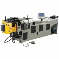
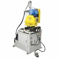



Electric Rotary Draw Tube Bender
The Electric Rotary Draw Tube Bender is a fully servo-driven CNC metal forming machine engineered for high-precision, repeatable tube and pipe bending. Replacing traditional hydraulic systems with absolute encoder-driven servomotors across all working axes, this platform delivers precise angular control, eliminates hydraulic thermal drift, and cuts fluid-related maintenance.
Built in-house with heavy-walled welded steel frames normalized to relieve internal stress before precision CNC machining, the machine ensures structural rigidity under peak bending loads. Integrated industrial CNC controllers execute multi-axis interpolation for bend, feed, and rotation, accommodating complex geometries in stainless steel, carbon steel, titanium, and aluminum alloys without wrinkling or excessive ovality.
Technical Specifications
|
Parameter |
Specification Range / Standard |
|
Max. Tube Diameter |
Up to 89 mm (3.5 inch) OD (customizable up to 114 mm) |
|
Max. Wall Thickness |
0.5 mm - 4.0 mm (material dependent) |
|
Max. Center Line Radius (CLR) |
Up to 250 mm (tooling dependent) |
|
Bending Axis Precision |
+/- 0.05 deg via direct-drive absolute encoder servo |
|
Feeding Axis Precision |
+/- 0.05 mm via rack-and-pinion / ball screw servo drive |
|
Rotation Axis Precision |
+/- 0.05 deg via high-precision planetary gearbox |
|
Controlled Axes |
Up to 8 Electric Axes (Y, B, C1, C2, Z1, Z2, A1, A2) |
|
Drive System |
Panasonic / Yaskawa AC Servo Motors with absolute encoders |
|
Control System |
IPC-based CNC with 15-inch multi-touch industrial screen |
|
Operating Voltage |
380V / 415V / 480V, 3-Phase, 50/60 Hz (customizable) |
Key Features
All-Electric Servo Architecture: Eliminates hydraulic oil reservoirs, pumps, and proportional valves. Power consumption drops by 40% during idle states, and thermal expansion fluctuations are removed from the bending cycle.
Rigid Meehanite Cast Iron Bending Head: Houses heavy-duty gear sets machined on 5-axis DMG Mori horizontal machining centers, maintaining tooth mesh tolerance within 0.01 mm to prevent backlash under high torque.
Dynamic Springback Compensation: Built-in algorithm measures material elastic recovery per bend angle and automatically adjusts over-bend parameters in real time based on historical batch data.
Anti-Wrinkle & Booster Support: Programmable pressure die booster (lagging or pushing) synchronizes material feed speed with the bending arm to eliminate wall thinning on tight-radius bends (R < 1.5D).
Modular Quick-Change Tooling Interface: Patented quick-release collet and mandrel extraction linkages allow tool changeovers in under 15 minutes without manual shimming.
Working Process
[ Raw Tube Loading ] -> [ Auto-Feeding (Z-Axis) ] -> [ Angular Rotation (B-Axis) ]
[ Mandrel Positioning ] -> [ Rotary Draw Bending (C-Axis) ] -> [ Auto-Unloading ]
Loading & Clamping: The raw tube is loaded onto the mandrel rod. The hydraulic or pneumatic collet clamps the tube against the pressure die and clamp die.
Feeding & Orientation: The carriage positions the tube longitudinally (Z-axis) and rotates it to the correct spatial angle (B-axis) for the next bend vector.
Bending Execution: The main bend arm (C-axis) rotates around the center former die while the pressure die assists material flow. If specified, the pressure die booster pushes the material forward to maintain wall thickness.
Mandrel Extraction: The mandrel retracts slightly before the clamp opens to prevent scratching the inner wall of the tube.
Part Release: The clamping and pressure dies open, clearing the finished component for unloading.
Applications
Automotive Exhaust & Fluid Lines: Forming complex multi-radius catalytic converter inlet pipes, turbocharger oil lines, and chassis structural members in 304/409 stainless steel.
HVAC & Refrigeration: Bending copper and aluminum evaporator/condenser return bends with zero cross-section reduction.
Aerospace & Defense: Processing high-strength titanium and Inconel fuel and hydraulic lines requiring tight tolerance compliance (+/- 0.05 deg).
Commercial Furniture & Fitness Equipment: High-speed batch production of structural steel frames with consistent bend repeatability across thousands of cycles.
Tooling & Configuration
Precision bending relies directly on correct tooling geometry matched to material yield strength. We manufacture matching tooling sets in-house using specialized alloy steels (H13, Ampco 18 bronze, or nitrided tool steel):
Mandrel Types: Single-ball, multi-ball (2 to 7 balls), or formed-end mandrels for ultra-thin walls.
Dies Included in Standard Package: 1x Bend Die, 1x Clamp Die, 1x Pressure Die, 1x Wiper Die, 1x Mandrel Body with matching balls.
Configuration Options: Single-stack, multi-stack (for multi-radius parts), and left-hand or right-hand bending configurations based on plant layout.
Customization
Specialized Carriage Lengths: Extended bed formats to accommodate tube lengths up to 6,000 mm.
Interfacing Automation: Integration with industrial robotic arms or automatic loading magazines for lights-out manufacturing cells.
Software Integration: Custom STEP/IGES file import capability supporting direct offline programming via CAD/CAM bending simulation software (e.g., TubeCAD, VGP).
Enclosure & Safety Options: Light curtains, safety interlocks, and full perimeter enclosures meeting CE and OSHA compliance standards.
Quality & Testing
Every machine undergoes a rigorous multi-stage verification process prior to factory dispatch:
Structural Inspection: Welded frames are tested via ultrasonic flaw detection (UT) and coordinate measuring machines (CMM) to verify dimensional squareness and weld integrity.
Axis Calibration: Laser interferometers verify linear positioning accuracy on feeding axes, while autocollimators measure rotational repeatability on bending heads.
Full-Load Factory Acceptance Test (FAT): Each machine runs a continuous 72-hour trial batch using client-specified sample material, verifying actual bend angle deviation, ovality, and wall thinning rates before crating.
Material Traceability: All primary castings, gearboxes, and servomotors carry traceable mill test certificates (MTC) and serial numbers logged in our ERP system.
FAQ
Q: What is the maximum wall thinning percentage achievable on tight radii (R = 1D)?
A: With the programmable pressure die booster active and correct multi-ball mandrel positioning, wall thinning can be controlled within 8% to 12% on standard 304 stainless steel tubes, preventing structural failure at the outer radius.
Q: How does the all-electric system compensate for material springback across different alloy batches?
A: The CNC system runs a closed-loop feedback calculation. After an initial test bend, the absolute encoder measures the exact relaxed angle. The controller calculates the springback delta and applies a real-time correction factor to the subsequent bends in that production batch.
Q: What utilities and shop floor preparation are required prior to machine installation?
A: The machine requires a stable 3-phase AC power supply (specified per regional voltage) and a dry, filtered compressed air supply (0.6-0.8 MPa) if pneumatic support options are selected. No hydraulic oil lines or chillers are required. Foundation requirements are standard industrial concrete flooring (minimum 150 mm thickness).
Q: Can existing tooling from hydraulic rotary draw benders be used on this machine?
A: Most standard tooling with matching shank dimensions and centerline heights can be adapted using custom adapter plates. However, for high-precision applications, newly matched tooling sets are recommended to match the exact clamp and pressure radii of the electric axis configuration.
Q: What is the typical lead time for standard models versus custom configurations?
A: Standard models (capacities up to 50 mm OD) are typically stocked or built within 30 to 45 days. Fully customized configurations featuring multi-stack tooling, extended beds, or robotic loading interfaces require 60 to 90 days from drawing approval to dispatch.
Q: What remote diagnostic and technical support options are available after delivery?
A: The industrial IPC controller features an embedded Ethernet port for secure remote VPN diagnostics. Our engineering team can log into the machine remotely to analyze servo error logs, update firmware parameters, and assist maintenance staff with real-time troubleshooting.
Hot Tags: electric rotary draw tube bender, China electric rotary draw tube bender manufacturers, suppliers, factory, CNC Carbon Steel Pipe Bender, CNC Small Diameter Tube Cutting Machine, CNC Thin Wall Pipe Bending Machine, Precision Alloy Tube Cutting Machine, Small Diameter Metal Tube Bending Machine, Square Tube Sawing Machine
You Might Also Like


Send Inquiry