

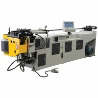


Mandrel Tube Bending Machine
Mandrel Tube Bending Machine
A mandrel tube bending machine is engineered to eliminate wall thinning, flattening, and wrinkling when processing thin-walled metal tubing at tight centerline radii (CLR). By positioning a flexible mandrel plug directly at the tangent point of the bend, internal support prevents structural collapse during plastic deformation.
Structural integrity is anchored by a normalized Meehanite cast iron bed and multi-axis CNC architecture, built to withstand continuous shift operations in stainless steel, carbon steel, titanium, and aluminum fabrication. In-house manufacturing processes incorporate floor-type CNC boring mills for frame machining and thermal stress relief on all structural weldments, ensuring geometric rigidity under high-torque loading.


Multi-Axis CNC Synchronization:
Closed-loop servo drives govern carriage feed (Y-axis), tube rotation (B-axis), and bend arm rotation (C-axis) to maintain angular repeatability within +/- 0.05 degrees.
Programmable Mandrel Extraction:
HMI-controlled hydraulic or pneumatic timing retracts the mandrel plug fractionally before bend completion, preventing inner-wall gouging.
Synchronous Pressure Die Assist:
A proportional booster cylinder pushes material into the bend zone synchronously with the bend die, suppressing outer-radius thinning and material tearing on thin-wall tubes.
Wiper Die Micro-Adjustment Mount:
Rigidly positions hardened steel or Ampco-18 bronze wiper dies immediately against the tangent point to prevent wave or wrinkle formation on tight radii.
Planetary Gear Transmission:
Direct-coupled heavy-duty gearboxes deliver high torsional output with zero backlash during high-wall-thickness carbon steel fabrication.
Technical Specifications
|
Model Series |
Max. Tube OD (mm) |
Max. Wall Thickness (mm) |
Min. CLR (Center Line Radius) |
Max. Axes |
Drive Architecture |
|
MB-CNC-50NC |
50 x 3.0 |
3.0 |
1.5 x OD |
3 (Y, B, C) |
Hydraulic / Servo Assist |
|
MB-CNC-89NC |
89 x 4.0 |
4.0 |
1.5 x OD |
Up to 5 |
Full Closed-Loop Servo |
|
MB-CNC-130NC |
130 x 6.0 |
6.0 |
1.5 x OD |
Up to 5 |
Servo / Heavy Hydraulic |
|
MB-CNC-220NC |
220 x 8.0 |
8.0 |
2.0 x OD |
Up to 5 |
Heavy-Duty Hydraulic |
Working Process
Loading & Referencing: Raw tubing is loaded over the mandrel rod until seated against the programmable material stop.
Clamping: The clamp die and pressure die firmly secure the tube blank against the main radius die.
Bending & Boosting: The bend arm rotates to the target angle (C-axis) while the pressure die booster applies longitudinal thrust.
Early Retraction: The internal mandrel retracts relative to the programmed percentage of the bend arc to clear the radius.
Release & Indexing: Dies unclamp; the carriage indexes the tube forward (Y-axis) and rotates to the secondary plane (B-axis) for multi-bend components.
Applications
Automotive Exhaust & Structural Chassis:
Processing 304/409 stainless steel tubing for exhaust headers, catalytic converter assemblies, and high-strength roll cages without cross-section ovality.
Aerospace Fluid Conduits:
Fabricating high-integrity titanium and Inconel tubing for hydraulic and environmental control systems requiring strict non-destructive testing (NDT) clearance.

HVAC & Industrial Heat Exchangers:
Producing uniform multi-bend copper and carbon steel headers and return U-bends for commercial refrigeration units.
Industrial Furniture & Architectural Framing:
Executing uniform tight-radius bends in thin-wall structural steel tubing and architectural handrails.
Tooling & Configuration
Successful mandrel performance requires precise tooling configuration matched to the material D/t ratio (diameter-to-thickness) and elongation factor.
Mandrel Selection:
Single-ball, multi-ball (for 1.5 x OD tight radii), and form-block mandrels machined from Ampco-18 aluminum bronze or hardened tool steel.
Matched Die Sets:
Complete tooling packages comprising Bend Die, Clamp Die, Pressure Die, and Wiper Die, laser-etched with part numbers and clearance dimensions.
Configuration Layouts:
Single-stack, multi-stack (for multi-radius components), and quick-change tooling cartridges to minimize setup downtime.

Machine frames undergo structural finite element analysis (FEA) during the engineering phase to minimize deflection under loads up to 250 kN. All structural weldments are thermally stress-relieved in a gas-fired annealing furnace prior to precision machining on floor-type CNC boring centers.
Prior to dispatch, every system completes a 72-hour continuous dry-cycle test followed by live material trials. Dimensional geometry, wall thinning ratios, and cross-section ovality are verified using ultrasonic thickness gauges and coordinate measuring machines (CMM). Inspection reports and material mill test certificates (MTC) ship with every capital unit.
Customization
Bed Length Extensions:
Customized machine beds configured to accommodate long tubular weldments (up to 6,000mm effective feed length).
Automation Cell Integration:
Robotic loading and unloading interfaces utilizing standard industrial fieldbus protocols (Ethernet/IP, Profinet).
Seam Detection Modules:
Integrated optical or mechanical sensors to detect and orient tube weld seams toward the neutral axis prior to clamping.
CAD/CAM Interface HMI:
Industrial touchscreens featuring DXF/IGES direct file import for automated program generation and simulation.
FAQ
Q: How do I determine whether my application requires a single-ball or multi-ball mandrel?
A: Tooling choice is dictated by the D/t ratio and the centerline radius. Tubing with a thin wall (t/OD < 0.05) or a tight radius (1.5 x OD) requires a multi-ball mandrel to maintain continuous internal support through the entire deformation arc. Standard thick-wall applications with wider radii utilize a solid plug or single-ball mandrel.
Q: What is the acceptable threshold for outer-wall thinning during bending?
A: For structural and pressure applications, outer-wall thinning should be controlled within 12% to 15%. Utilizing a proportional pressure die booster actively feeds material into the bend zone, keeping thinning within acceptable engineering limits without material tearing.
Q: How does the CNC system compensate for material springback in high-tensile steels?
A: The controller incorporates programmable over-bend parameters. By inputting the specific tensile strength, yield strength, and elastic modulus of the batch material into the HMI, the system applies a calibrated over-bend degree to counteract elastic recovery, ensuring the final formed angle meets the target within +/- 0.05 degrees.
Q: What is the standard manufacturing lead time for custom tooling sets?
A: Standard round tube tooling sets (Bend, Clamp, Pressure dies and single mandrel) require 15 to 20 working days. Complex multi-stack or asymmetrical profile tooling requires 25 to 30 days, which includes physical sample verification and trial bending reports.
Q: How are spare parts and technical support handled internationally?
A: All core electronic and hydraulic elements-including Siemens/Schneider PLCs, Rexroth proportional valves, and Yaskawa servo drives-are globally sourced industrial standards. Remote diagnostics are supported via secure industrial Ethernet, and replacement mechanical wear parts are dispatched directly from inventory within 48 hours.
Q: What are the baseline utility and operating requirements for installation?
A: Standard units operate on 3-phase 380V/480V, 50/60Hz power supplies. Hydraulic-intensive configurations require clean ISO VG 46 hydraulic oil and an ambient operating environment between 5°C and 45°C. Pneumatic-assisted axes require a regulated compressed air supply of 0.6 to 0.8 MPa.