

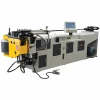




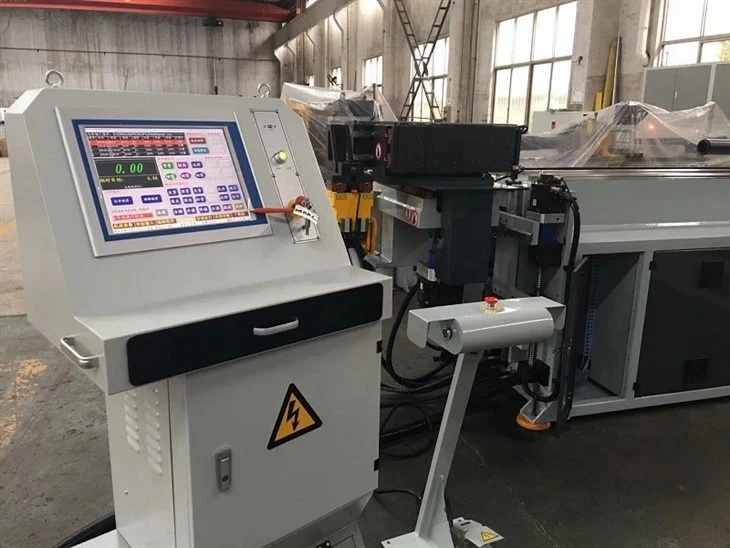
CNC Electric Tube Bending System
The CNC Electric Tube Bending System operates entirely on multi-axis absolute servo drives, replacing conventional hydraulic circuits with direct-drive mechanical execution. This architecture eliminates thermal oil drift and fluid contamination while delivering continuous angular precision.
Manufacturing Foundation: Built around a stress-relieved, heavy-wall monolithic steel weldment, the machine bed undergoes annealing and precision CNC boring in a temperature-controlled facility to guarantee structural rigidity under loads up to 150 kN. Every frame is laser-interfered for geometric alignment prior to electrical assembly, adhering strictly to ISO 9001 quality management standards.
Technical Specifications
|
Parameter Category |
Specification Details |
|
Max. Tube Diameter |
Φ 10 mm - Φ 89 mm (Customizable up to Φ 150 mm) |
|
Max. Wall Thickness |
0.5 mm - 4.0 mm (Material dependent) |
|
Bending Axes |
5 to 9 Electric Axes (Y, B1, B2, C1, C2, X1, X2, Z) |
|
Single Radius (CLR) |
Min. 1 x OD (Application specific) |
|
Bending Precision |
± 0.05 mm (Linear) / ± 0.05° (Rotational) |
|
Drive System |
AC Absolute Servo Motors with Planetary Reducers |
|
Control System |
Industrial PC with Touchscreen HMI & 3D Simulation |
|
Power & Safety Compliance |
380V / 415V, 50/60Hz, 3-Phase; CE & UL Certified Electrical Architecture |
Key Features
All-Electric Servo Architecture: Eliminates hydraulic power units, reducing energy consumption by 40% during idle states and removing oil temperature variance from production cycles.
Closed-Loop Springback Compensation: Integrated sensors measure immediate material recovery post-bend, allowing the control system to automatically adjust over-bend angles in real-time.
Multi-Stack Tooling Capacity: Accommodates up to three different radii plus a roll-bending stack on a single tooling tower, executing complex geometries without manual tool swaps.
Interference Collision Detection: The onboard industrial PC executes pre-bend 3D simulations of the tube against machine components, preventing tooling crashes before production runs.
Dynamic Pressure Booster: Programmable carriage boost applies axial force during tight-radius bends, minimizing wall thinning on the outer radius and wrinkling on the inner radius.
Working Process
Material Loading: Raw tubular stock is manually or automatically loaded into the pneumatic collet chuck on the feed carriage (X-axis).
Feeding & Rotation: The carriage positions the tube longitudinally (Y-axis) and rotates it to the precise polar angle (B-axis) for the initial bend node.
Mandrel Positioning: The internal mandrel extends forward past the tangent point to support the inner tube wall against ovalization.
Bending Execution: The pressure die and clamp die lock the tube against the bend die, while the servo-driven bend arm (C-axis) sweeps to the programmed angle.
Retraction & Unclamping: The mandrel retracts slightly prior to completion to strip the tube, and dies open for the next indexing cycle.
Applications
Automotive Exhaust Systems: Processing aluminized and stainless steel tubing for catalytic converter assemblies and tailpipe routing with tight bend radii.
HVAC&R Components: Bending copper and aluminum evaporator/condenser return bends with zero wall collapse and tight pitch tolerances.
Aerospace Fluid Lines: Fabricating thin-walled titanium and inconel hydraulic conduits requiring strict adherence to aerospace cleanliness and straightness standards.
Industrial Furniture & Equipment: Forming tubular steel frames for hospital beds, fitness equipment, and commercial shelving with consistent aesthetic finishes.
CNC Tube Bending Machine Tooling & Mandrel Configuration
Achieving optimal bend geometry requires matched tooling configurations tailored to specific material tensile strengths and elongation properties.
Bend Dies & Clamp Dies: Manufactured from forged alloy steel (H13 or 40Cr), vacuum heat-treated to HRC 58-62, and precision CNC ground to match exact tube ODs.
Mandrels: Hard-chrome plated flexible steel mandrels with 3 to 7 links, configured based on the CLR-to-diameter ratio to eliminate inner-radius wrinkling.
Wiper Dies: Bronze or Ampco metal wiper dies positioned immediately ahead of the tangent point to prevent material bulging on tight-radius bends.
Pressure Dies: Servo-synchronized assist dies that match feed velocity to eliminate scratch marks and uneven material draw.
Customization
Automation Integration: Interface compatibility with 6-axis loading/unloading articulated robots or gantry loading systems via standard discrete I/O or Profinet protocols.
Extended Bed Lengths: Carriage travel distance extensible from standard 3000 mm up to 6000 mm for extra-long tubular chassis components.
Punching/Cutting Integration: Optional inline hydraulic or servo-driven hole-punching units integrated directly into the bending cycle before or after the bend sequence.
Quality & Testing
Quality verification follows strict in-house inspection protocols before equipment dispatch:
Geometric Calibration: Laser interferometer tracking verifies linear axis positioning accuracy over full bed lengths.
Load Testing: Continuous dry-cycle running for 48 hours under simulated operational loads to monitor thermal stability of electrical cabinets and servo drives.
Sample Validation: Trial runs using client-supplied raw material lots; finished bends are inspected on a 3D Coordinate Measuring Machine (CMM) to provide comprehensive inspection reports.
Compliance Standards: Electrical panels built in accordance with CE and UL safety specifications, utilizing industrial safety relays, interlocked safety gates, and light curtains. Factory Acceptance Testing (FAT) protocols are available for client sign-off prior to shipment.
FAQ
Q: How does the all-electric system compensate for material batch variations and springback?
A: The control software incorporates an adaptive springback database. When a new batch of tubes is loaded, an initial sample piece is run. The control unit measures the actual angular recovery via integrated encoders, calculates the deviation, and automatically applies a correction factor to all subsequent bends in that batch.
Q: What is the maximum tool changeover time between different tube diameters?
A: Using quick-change hydraulic or manual wedge clamping systems on the tooling stack, a complete changeover of bend dies, pressure dies, and mandrels typically takes between 15 to 25 minutes.
Q: Can this system handle square or rectangular tubing?
A: Yes. By replacing standard round-tube tooling sets with matched square/rectangular profile dies and adjusting the non-rotational axis parameters, the machine processes hollow structural sections (HSS) with proportional torque control.
Q: What CAD file formats are compatible with the control software?
A: The onboard IPC natively imports standard .STEP, .IGES, and .DXF files. The software extracts centerline coordinates, bend angles, and straight lengths automatically, converting them into executable machine code.
Q: What utility requirements are necessary on the factory floor?
A: The machine requires a standard 3-phase industrial power supply (380V/415V) and a compressed air line supplying 0.6-0.8 MPa for pneumatic clamping functions. No chilled water or hydraulic ring mains are required.
Q: What is the standard warranty and post-sale technical support process?
A: All core mechanical assemblies and servo motors carry a 12-month standard warranty, backed by available global spare parts inventory. Remote diagnostic support is embedded via a secure industrial ethernet connection, allowing our engineers to troubleshoot software and PLC parameters globally within 24 hours.
Hot Tags: cnc electric tube bending system, China cnc electric tube bending system manufacturers, suppliers, factory, CNC Automatic Circular Saw Machine, CNC High Speed Tube Bending Machine, Precision Alloy Tube Cutting Machine, Rotary Draw Metal Tube Bending Machine, Servo Metal Tube Bending Machine, Tube Cut to Length Circular Saw Machine
You Might Also Like


Send Inquiry