



Cold Saw Machine
Product Overview
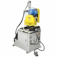
Industrial cold circular saws utilize high-speed steel (HSS) or tungsten carbide-tipped (TCT) saw blades rotating at controlled low RPMs to shear metal rather than grind it. This mechanical action transfers cutting heat into the chips rather than the workpiece or blade, resulting in a clean, burr-free cold-cut finish tailored for high-speed industrial lines.
Built with heavy-gauge welded steel frames and precision-ground linear guide rails, these heavy-duty machines handle continuous multi-shift production in tube mills, metal service centers, and structural fabrication plants. Drive systems feature heavy-duty helical gearboxes coupled with variable frequency drives (VFD) or servo motors to match blade surface speed (SFM) precisely to specific material hardness grades.
Manufacturing operations rely on in-house CNC boring mills, large-scale gantry milling machines, and precision grinding equipment to machine main castings and saw heads. This internal machining control maintains strict perpendicularity between the blade axis and feeding stock, achieving square cuts within +/- 0.1 mm tolerances prior to downstream welding or assembly.


Backlash-Free Gear Transmission:
Helical gearboxes hardened to HRC 58-62 eliminate mechanical play during tooth engagement, preventing micro-chipping on TCT blade tips during breakthrough phases.
Hydraulic Clamping Vices:
Split-jaw clamping design secures both sides of the cut line simultaneously, preventing material vibration, edge deformation, and burr formation on thin-walled tubing.
Programmable CNC Feeding:
Servo-driven ball screws handle material positioning up to 1,000 mm per stroke with multi-index capability for long stock processing.
Mist Lubrication Integration:
Solenoid-actuated micro-lubrication systems inject controlled droplets of synthetic cutting fluid directly onto the blade tooth pathway, extending TCT tip life by 40% compared to flood coolant systems.
Integrated Chip Conveyor & Management:
Built-in scraper chains and pneumatic chip blowers prevent ferrous scrap accumulation inside the cutting zone during high-speed production runs.
Technical Specifications
|
Model Designation |
CS-65NC |
CS-100NC |
CS-150NC |
|
Max. Round Tube Capacity |
OD 15 - 65 mm |
OD 20 - 100 mm |
OD 30 - 150 mm |
|
Max. Square Tube Capacity |
50 x 50 mm |
80 x 80 mm |
120 x 120 mm |
|
Max. Solid Bar Capacity |
Dia. 45 mm |
Dia. 70 mm |
Dia. 110 mm |
|
Blade Dimensions (OD x Bore) |
285 x 32 mm |
360 x 32 mm |
450 x 50 mm |
|
Spindle Speed Range |
30 - 180 RPM (Adjustable) |
25 - 145 RPM (Adjustable) |
20 - 110 RPM (Adjustable) |
|
Main Motor Power |
5.5 kW |
11 kW |
18.5 kW |
|
Feeding Servo Power |
1.5 kW |
2.0 kW |
3.0 kW |
|
Cutting Length Tolerance |
+/- 0.1 mm |
+/- 0.1 mm |
+/- 0.15 mm |
|
Operating Air Pressure |
0.6 - 0.8 MPa |
0.6 - 0.8 MPa |
0.6 - 0.8 MPa |
|
Machine Weight |
1,800 kg |
3,200 kg |
5,500 kg |
Working Process
Material Loading: Bundled or single tubes/bars load onto the inclined magazine loader, where mechanical escapement arms isolate and feed stock onto the infeed roller table.
Servo Positioning: The servo-driven gripper carriage clamps the leading edge of the material and indexes it forward against a mechanical or optical zero-stop sensor to establish the exact cut length.
Dual-Side Clamping: Vertical and horizontal hydraulic clamping cylinders secure the stock tightly against V-shaped hardened jaws immediately adjacent to the saw blade exit plane.
Controlled Saw Feed: The saw head advances along precision linear guides via a proportional hydraulic cylinder or ballscrew slide, with feed rates dynamically adjusted based on cutting load feedback from the spindle motor inverter.
Retraction & Discharge: Upon stroke completion, the blade retracts rapidly, vice jaws release, and the cut part drops onto the sorting trap or outfeed conveyor while remnant ends are ejected into scrap bins.
Applications
Automotive Exhaust & Chassis Tubes:
Processing high-strength low-alloy (HSLA) steel tubes ranging from OD 25 mm to 89 mm with clean, square ends ready for automated robotic welding cells.
Structural Steel Profiles:
Cutting carbon steel rectangular hollow sections (RHS), channels, and angles for construction scaffolding and heavy equipment frames without thermal distortion.
Stainless Steel Fluid Lines:
Precision cutting of 304/316L sanitary tubes used in dairy, pharmaceutical, and chemical processing facilities, eliminating internal burrs that trap particulate matter.
Solid Bar Stock Preparation:
Slicing alloy steel and bearing steel billets prior to hot forging or CNC turning operations, ensuring flat face geometry to reduce initial facing tool wear.
Tooling & Configuration
TCT Saw Blade Selection:
Compatible with standard carbide-grade blades (PVD-coated TiAlN or cermet-tipped) designed for specific material tensile strengths (600 MPa to 1200 MPa). Quick-change arbors allow blade swaps within 5 minutes.
Jaw Inserts:
Modular, wire-cut EDM hardened tool steel jaws matched to specific tube diameters (OD +/- 0.2 mm) to maximize gripping surface area without crushing thin-wall profiles.

Material Handling Modules:
Optional bundle loaders, gravity sorting tables, length-measuring digital readouts, and automatic inkjet part-marking units configurable per line layout.
Electrical Architecture:
Standard PLC and touch-screen HMI configurations utilize Siemens or Schneider components, supporting Modbus/Profinet protocols for plant SCADA integration.
Customization
Custom Clamping Profiles:
Engineering departments design custom multi-cavity jaw sets for simultaneous cutting of nested multi-tube layouts or specialized asymmetric extrusion profiles.
01
Extended Feeding Strokes:
Servo feed carriages expandable from standard 1,000 mm strokes up to 3,000 mm single-index travel for long-length structural applications.
02
In-Line Automation Interfaces:
Mechanical and electrical handshakes built to interface seamlessly with existing tube mills, deburring brushes, washing machines, and bending cells.
03
Special Voltage & Safety Standards:
Control panels built to conform to regional electrical requirements, including UL/CSA certification packages for North American markets and CE compliance for Europe.
04
Quality & Testing
Structural Frame Annealing: Fabricated weldments undergo thermal stress-relieving annealing furnaces at 650 deg C for 8 hours prior to machining, preventing long-term geometric distortion under continuous heavy loads.
Geometric Inspection: Laser interferometer calibration is performed on all linear axes and spindle runout tests verify axial and radial play remain under 0.01 mm before sign-off.
Factory Acceptance Testing (FAT): Every machine undergoes a 72-hour continuous dry-run test followed by actual production cutting trials using customer-supplied raw material samples to verify burr limits and tolerance repeatability.
Traceability Documentation: Each shipment includes material test reports (MTRs) for structural steel components, electrical schematics, calibration certificates, and 3D spare parts manuals.
FAQ
Q: What is the typical blade life before TCT teeth require resharpening?
A: Blade life depends on material hardness, wall thickness, and cutting speed, but standard carbide blades typically achieve 3,000 to 6,000 cuts on carbon steel tubes (OD 50 mm, 2 mm wall) before requiring professional re-grinding on a CNC tool grinder.
Q: How does an industrial cold circular saw prevent burrs compared to abrasive friction saws or band saws?
A: Industrial cold circular saws utilize positive rake-angle carbide teeth that shear the metal cleanly in a single stroke at low speeds. This mechanical action produces thick chips that carry away cutting heat, leaving an edge free of thermal discoloration, heavy burrs, or sharp jagged edges.
Q: Can this machine process non-ferrous metals like aluminum and copper?
A: Yes. By swapping to a specialized negative-rake TCT blade configuration, adjusting spindle speeds to higher RPM ranges, and using oil-mist lubrication, the machine cuts aluminum extrusions, copper bars, and brass tubes cleanly without material adhesion to the blade teeth.
Q: What utilities are required on the factory floor for installation?
A: The machine requires a 3-phase industrial power supply (typically 380V/480V, 50/60Hz), a compressed air supply delivering 0.6 - 0.8 MPa at 200 L/min for pneumatic clamping and chip clearance, and a designated floor space anchored with leveling pads.
Q: What level of operator training is required to run the CNC control interface?
A: Operators require basic mechanical literacy and can master the touch-screen HMI within one shift. The interface stores up to 99 cutting recipes, allowing operators to recall preset parameters for length, speed, and batch counts instantly.
Q: What spare parts should be stocked locally to prevent extended downtime?
A: Essential consumable spares include matched sets of clamping jaw inserts, replacement TCT saw blades, pneumatic solenoid valves, wiper seals, and primary drive belts. Critical electronic and mechanical components ship from stock with standard 3-5 day international delivery windows.