

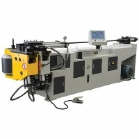




Multi-Stack Tube Bending Machine
The multi-stack tube bending machine executes complex multi-radius components within a single loading cycle. By stacking multiple tooling tiers vertically or horizontally, the machine shifts between different centerline radii (CLR) and bending directions without manual tooling changeovers.
Driven by multi-axis CNC architecture, the system coordinates carriage rotation, feeding, and bending via absolute servo drives. Heavy-duty cast Meehanite frames absorb torsional stress during high-load stainless steel and carbon steel forming. This configuration suits high-mix, high-volume production lines in automotive exhaust fabrication, HVAC manufacturing, and aerospace structural assembly where cycle time and positional repeatability directly dictate manufacturing margins.
Technical Specifications
The CNC Servo Electric Tube Bending Machine utilizes multi-axis absolute servo motor drives (Siemens Sinumerik CNC architecture) to execute high-precision, programmable cold bending operations for metal tubes and profiles. Operating without hydraulic oil systems, this architecture eliminates thermal drift, reduces energy consumption by up to 45%, and achieves angular repeatability of +/-0.05 deg. Built with a rigid Meehanite cast iron frame and finite element analysis (FEA) optimized stress distribution, the machine handles complex multi-radius geometries across stainless steel, carbon steel, copper, and aluminum alloys for tier-1 manufacturing environments. Built under ISO 9001:2015 quality management standards and fully compliant with CE safety directives.
Key Features
|
Specification Item |
Standard Parameters |
|
Max. Tube Diameter (OD) |
Dia 10 mm - Dia 114 mm (Model-dependent) |
|
Max. Wall Thickness |
0.5 mm - 6.0 mm (Material dependent) |
|
Bending Method |
Rotary Draw Bending / Mandrel Bending / Push Bending |
|
Tooling Stack Levels |
Up to 4 Stacks (Multi-radius / Fixed + Variable combination) |
|
Max. Bending Angle |
180 deg + Springback compensation margin |
|
Axis Control |
5-Axis CNC (Y: Feeding, B: Plane Rotation, C: Bending, X1/X2: Horizontal/Vertical Shift) |
|
Bending Precision |
+/- 0.05 deg |
|
Feeding Precision |
+/- 0.05 mm |
|
Drive System |
AC Servo Motors coupled with precision planetary gearboxes |
|
Control System |
Industrial IPC, Windows-based 3D simulation software, Ethernet/USB interface |
|
Hydraulic System Pressure |
14 MPa - 21 MPa with water-oil cooling heat exchanger |
Key Features
Multi-Stack Tooling Architecture: Accommodates up to four different radii or tool configurations on a single stack slide. Reduces part handling, eliminates secondary clamping errors, and shortens per-part cycle times for complex geometries.
Rigid Meehanite Cast Bed: The machine base utilizes stress-relieved Meehanite cast iron, machined on 5-axis gantry milling centers in a single setup to maintain structural alignment and resist deflection under peak loads up to 250 kN.
Closed-Loop Servo Control: Eliminates hydraulic drift through absolute encoder feedback on all primary bending and feeding axes, maintaining positional repeatability over extended operational shifts.
Dynamic Pressure Booster & Mandrel Extractor: Programmable early mandrel extraction limits internal tube friction, preventing wall thinning and wrinkling on tight-radius bends (R <= 1.5D).
Off-Line 3D Programming Interface: Operators import STEP or IGES CAD files directly into the industrial IPC. The software automatically calculates elongation factors, springback parameters, and interference zones prior to physical execution.
Working Process
[ Raw Material Loading ]
|
v
[ Hydraulic Front Collet Clamping ]
|
v
[ Mandrel Positioning & Internal Support ]
|
v
[ Servo-Driven Carriage Feeding (Y-Axis) & Rotation (B-Axis) ]
|
v
[ Multi-Stack Stack Shift (X-Axis) to Target Radius ]
|
v
[ Rotary Draw Bending Execution (C-Axis) with Pressure Die Assist ]
|
v
[ Mandrel Extraction & Part Unloading ]
Material Loading: The operator places the raw tubular stock into the hydraulic collet.
Clamping & Support: The front collet clamps the tube while the internal mandrel advances to the tangent point to prevent cross-sectional flattening.
Feeding & Rotation: Servo motors drive the carriage to position the tube longitudinally and rotationally for the first bend.
Stack Selection: The stack slide shifts horizontally or vertically to align the specified tooling radius with the bend die centerline.
Bending: The main bend arm rotates while the pressure die booster applies synchronized linear force, keeping material tension uniform along the outer wall.
Extraction & Release: The mandrel retracts slightly ahead of the completion angle, the clamp die opens, and the finished component releases.
Applications
Automotive Exhaust Systems: Forms complex catalytic converter pipes and multi-radius tailpipes from 409L and 304 stainless steel tubing without cross-section ovality exceeding 3 percent.
Commercial HVAC & Refrigeration: Bends thick-walled copper and aluminum distribution headers, minimizing thinning at the bend extrados to sustain internal operating pressures up to 4.5 MPa.
Aerospace Fluid Lines: Processes high-strength titanium (Grade 9) and Inconel alloy tubing for aircraft hydraulic systems, requiring strict adherence to bend radius tolerances (CLR = 1D to 3D).
Commercial Furniture & Fitness Equipment: Handles high-tensile structural steel tubes (Q235 / Q355) for gym frames and ergonomic office furniture, executing compound bends in a continuous sequence.
Tooling & Configuration
Precision bending relies entirely on the kinematic coordination of five primary tooling components, manufactured in-house from high-grade alloy tool steels (H13, Cr12MoV) through vacuum heat treatment to achieve hardness levels of HRC 58 - 62.
|
Tooling Component |
Function |
Material Specification |
|
Bend Die (Form Die) |
Defines the inner radius of the bend; matches the outer diameter of the tube. |
Forged H13 Tool Steel, Vacuum Quenched |
|
Clamp Die |
Grips the tube firmly against the bend die during rotation. |
Nitided Alloy Steel with serrated gripping face |
|
Pressure Die |
Follows the tube during the bend to push material into the bend zone, preventing excessive wall thinning. |
Ampco Bronze or Hardened Tool Steel |
|
Wiper Die |
Prevents wrinkling on the inside of the bend (intrados) by resting tightly against the bend die tangent point. |
Ampco 18 Aluminum Bronze (reduces friction galling) |
|
Mandrel & Balls |
Supports the interior wall of the tube to prevent collapse or flattening. Link balls provide flexible internal support through tight radii. |
20CrMnTi, Carburized and Hardened |
Customization
Standard models cover the majority of industrial requirements, but application-specific variations are engineered upon request:
Extended Bed Lengths: Carriage travel distance expandable from standard 3000 mm up to 6000 mm for long structural members.
Specialized Tooling Profiles: Custom multi-stack combinations for non-circular geometries (oval, square, rectangular, and D-tubes).
Automation Integration: Robotic loading/unloading arms and automatic bundle feeding magazines interface directly with the machine's PLC via digital I/O or Profinet protocols.
Pneumatic / Hydraulic Boosters: Secondary booster configurations added to the carriage slide for tight-radius bending of high-strength alloys.
Quality & Testing
Structural integrity and mechanical precision are verified prior to factory shipment through strict internal verification protocols:
Bed Machining & Annealing: All structural weldments undergo high-temperature annealing (600 deg C to 650 deg C) to release residual welding stress, followed by machining on large-scale CNC floor boring machines.
Laser Interferometer Calibration: Linear and rotational axes are calibrated using Renishaw laser interferometers to verify positioning accuracy and eliminate backlash.
Continuous Load Run-Test: Each machine completes a 72-hour dry-run endurance test followed by a live material test using customer-supplied tube samples.
Dimensional Inspection: Finished sample bends are measured using Faro arm portable CMM systems to verify CLR radius, wall thickness reduction rates, and angle springback compensation.
Compliance Certification: Electrical cabinets conform to CE/UL safety standards, utilizing Schneider and Siemens low-voltage components.
fAQ
Q: How does the multi-stack system reduce per-part production time in high-mix manufacturing?
A: The multi-stack design houses 2 to 4 different radius tools or stacking configurations on a single vertically/horizontally shifting slide. When a component requires transitions between different CLR radii or complex compound angles, the CNC system shifts the stack dynamically without stopping the production cycle or requiring manual die swaps. This eliminates setup downtime between radius changes and reduces material handling errors.
Q: What is the maximum wall thinning rate achievable when bending thin-walled stainless steel tubes?
A: With proper setup utilizing a multi-ball mandrel, a matching wiper die, and synchronized pressure die boost, the wall thinning rate on the outer radius (extrados) is controlled within 10 percent to 15 percent for tubes with a D/t (diameter-to-thickness) ratio of 20:1. The exact threshold depends on material elongation properties and bend radius tightness (CLR >= 1.5D).
Q: How does the control system handle material springback across different alloy batches?
A: The industrial IPC runs a closed-loop springback compensation algorithm. Operators input material tensile strength and elongation data into the HMI. During initial trial bends, absolute encoders measure actual angular recovery. The software automatically applies an offset correction angle to subsequent bends, ensuring consistent final geometry despite raw material hardness variations between batches.
Q: What maintenance is required for the hydraulic and servo-electric drive systems?
A: Routine maintenance involves checking hydraulic fluid levels and operating temperatures (maintained below 55 deg C via the integrated water-oil heat exchanger), inspecting wiper and mandrel lubrication systems, and greasing linear guideways every 200 operational hours. The centralized lubrication system automatically dispenses metered grease to critical ballscrews and bearings based on cycle counts.
Q: Can this machine integrate with automated robotic loading cells?
A: Yes. The control architecture includes standard hardware interfaces (Ethernet/IP, Profinet, and hardwired dry-contact I/O) designed to communicate with industrial gantry loaders or 6-axis articulated robotic arms. Safety interlocks conform to ISO 13849-1 standards, allowing synchronized communication for automated material loading, clamping, and part extraction.
Q: What documentation and factory acceptance testing (FAT) are provided prior to delivery?
A: Each machine includes a complete technical dossier: electrical schematics, hydraulic circuit diagrams, PLC backup files, and calibration certificates. Prior to shipment, customers are invited for a Factory Acceptance Testing (FAT) session where sample parts are processed using production-grade raw materials to verify all agreed-upon geometric tolerances and cycle-time metrics.
Request a Project Feasibility Evaluation & Quotation
Procurement timelines for capital machinery require exact validation of part geometry, cycle times, and tooling lifespans. Our engineering team reviews incoming CAD files to provide a comprehensive production feasibility report within 48 hours.
To initiate a technical review, please provide the following parameters in your inquiry:
Part Geometry: STEP or IGES 3D CAD file of the tubular component.
Material Data: Tube Outer Diameter (OD), wall thickness, and material grade (e.g., SUS304, Q235, Titanium Grade 9).
Production Volume: Annual batch size and target cycle time requirements.
Hot Tags: multi-stack tube bending machine, China multi-stack tube bending machine manufacturers, suppliers, factory, Automatic Servo Tube Cutting System, Automatic Tube Bending Machine, Automatic Tube Cutting and Tapping Machine, CNC Oval Tube Cutter, CNC Square Pipe Cutter, Servo Precision Tube Cutting Machine
Next
No InformationYou Might Also Like


Send Inquiry