

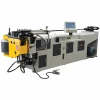



Variable Radius Tube Bending Machine
The variable radius tube bending machine executes continuous radius transitions along a single tubular workpiece without reloading or secondary cutting operations. By dynamically shifting the bending pivot point and adjusting the pressure die feed rate during the cycle, the system handles complex geometries required in modern automotive exhaust and structural chassis fabrication.
Built on a rigid, stress-relieved welded steel frame, the machine minimizes torsional deflection during high-load stainless steel and titanium bending. Integrated multi-axis CNC architecture synchronizes mandrel advancement, booster pressure, and radius shifting to maintain cross-sectional circularity and prevent wall collapse.
Technical Specifications
|
Parameter |
Standard Specification |
Extended Capacity / Custom |
|
Max. Tube Diameter (OD) |
51 mm - 89 mm |
Up to 114 mm |
|
Max. Wall Thickness |
3.0 mm (Carbon Steel) |
4.0 mm |
|
Centerline Radius (CLR) Range |
Variable: 2D to 30D (Continuous shift) |
Ultra-tight configurations available |
|
Max. Bending Angle |
180 degrees |
190 degrees |
|
Controlled CNC Axes |
6 Axes (Feed, Rotation, Bending, Shift, Pressure Die, Mandrel) |
Up to 9 Axes |
|
Drive System |
Absolute Servo Motors with Planetary Gearboxes |
Direct-drive torque motors for rotary axis |
|
Operating Voltage |
380V / 415V, 3-Phase, 50/60Hz |
Custom configurations per regional grid |
Key Features
Dynamic Radius Transition Mechanism: Servo-driven mechanical slides alter the pivot geometry during the draw-bending cycle, allowing seamless transitions from tight bends to large radii or straight sections on one component.
Closed-Loop Springback Compensation: Real-time angular feedback sensors measure material recovery post-bend and automatically adjust over-bend angles within the PLC cycle.
Synchronized Booster Push: Programmable carriage booster applies axial thrust matching the neutral axis speed, eliminating excessive wall thinning on outer radii when processing thin-walled aerospace tubing.
Heavy-Duty Rigid Bed: Base frames undergo thermal annealing and precision CNC milling in a single setup to maintain alignment tolerances under sustained industrial workloads.
Working Process
Loading & Material Clamp: The tube feeds onto the mandrel shank; the clamp die and pressure die secure the material against the main bend die.
Mandrel Positioning: The internal mandrel plug extends past the tangent point to support the inner wall against buckling.
Dynamic Bending & Radius Shift: The main spindle rotates the bend die while the variable radius slide shifts position according to the programmed CNC coordinate profile.
Booster Assist: The carriage pushes material forward dynamically to feed metal into the bending zone, reducing thinning.
Extraction & Unclamping: Dies retract, the mandrel indexes slightly to clear internal burrs, and the finished component unloads.
Applications
Automotive Exhaust Systems: Forming complex tailpipes and catalytic converter inlet tubes with continuous smooth radius shifts to optimize exhaust gas flow dynamics.
Aerospace Ducting: Manufacturing lightweight aluminum and Inconel fluid transport lines requiring strict weight-to-strength ratios and zero wrinkling.
Motorsports Roll Cages: Producing complex structural chassis tubing where continuous multi-radius bends eliminate joints and weld intersections.
Industrial Heat Exchangers: Fabricating serpentine coil geometries requiring tight return bends coupled with extended straight legs.
Tooling & Configuration
Matched Tooling Sets: Bending dies, clamp dies, pressure dies, and wiper dies manufactured from high-grade alloy tool steel (H13 or Ampco bronze inserts) matching the exact tube OD and centerline radius profile.
Mandrel Types: Selection of plug mandrels, formed mandrels, or multi-ball flexible mandrels depending on the D ratio and wall thickness of the application.
Quick-Change Tooling Interface: Hydraulic quick-release mountings reduce setup and calibration downtime between different production runs.
Customization
Multi-Stack Tooling: Integrates multiple radius dies on a single stack for parts requiring alternating fixed and variable radii without manual tool swaps.
Cell Integration: Compatible with robotic loading/unloading arms and automated measuring systems via industrial Ethernet communication protocols (Profinet / Ethernet/IP).
Extended Bed Lengths: Custom carriage travel distances to accommodate oversized structural tubes up to 6,000 mm.
Quality & Testing
Frame Machining Integrity: Structural weldments undergo stress-relief annealing followed by machining on large-scale floor boring mills to guarantee sub-millimeter parallelism across all slide rails.
Factory Acceptance Testing (FAT): Every machine undergoes a 72-hour dry-run endurance test followed by a live material test using customer-supplied tube samples to verify angular repeatability and radius transition smoothness.
Inspection Metrology: Critical components and finished assemblies are verified using laser trackers and coordinate measuring machines (CMM) before crating.
FAQ
Q: How does the machine prevent wall wrinkling during a variable radius transition?
A: The internal multi-ball mandrel supports the inner tube wall right at the tangent point, while the programmable booster carriage applies axial compression. This combined force eliminates compressive wrinkles on the inner radius and prevents excessive thinning on the outer wall.
Q: What is the minimum straight length required between two different variable radii?
A: The minimum tangent distance depends on the tube OD and the clamping length requirements of the tooling. Generally, a straight section equal to 1.5 x OD is recommended, though zero-tangent capability can be engineered with specialized segmented tooling.
Q: How is springback handled when switching radius profiles on high-strength alloys?
A: The CNC control software utilizes material-specific elasticity databases and real-time angular feedback sensors. After an initial test bend, the system calculates the actual springback angle and automatically updates the over-bend correction factor for subsequent production pieces.
Q: What utilities and infrastructure are required to install this machine?
A: The machine requires a standard industrial 3-phase power supply (typically 380V to 415V), a stable compressed air supply (6 to 8 bar) for pneumatic clamping functions, and a dedicated foundation or reinforced concrete floor capable of supporting the static and dynamic loads of the specific bed size.
Q: How long does a typical tooling changeover take?
A: Equipped with hydraulic quick-change clamping and pre-calibrated modular die sets, operator changeover between different tube diameters and radius configurations takes approximately 20 to 30 minutes.
Q: What file formats does the CNC controller accept for programming?
A: The industrial PC controller accepts standard XYZ or YBC coordinate data input, direct STEP or IGES CAD file imports via USB or network transfer, and manual conversational programming for shop-floor modifications.
Hot Tags: variable radius tube bending machine, China variable radius tube bending machine manufacturers, suppliers, factory, Automatic Tube Cutting and Tapping Machine, CNC Industrial Tube Cutter, Double Head Pipe Bender, Fully Automatic Pipe Cutting Machine, Hydraulic Stainless Steel Tube Bending Machine, Servo Precision Tube Cutting Machine
You Might Also Like



Send Inquiry