

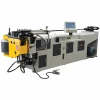




Multi-Die Tube Bending Machine
Multi-Die Tube Bending Machine - Technical Product Specification & Procurement Guide
A Multi-Die Tube Bending Machine integrates multiple tooling stacks (stack-and-multi-radius configurations) on a single shifting carriage or bending slide. This architecture allows operators to execute different centerline radii (CLR), compound angles, or multi-diameter transitions on a single tubular component within one automated loading cycle.
Eliminating manual die swaps between bends reduces part handling, removes cumulative positioning errors, and cuts cycle times by up to 35% for complex geometries such as automotive exhaust routing, aerospace fluid lines, and HVAC manifolds. Built on a heavy-gauge, stress-relieved welded steel frame, the machine maintains structural rigidity under high bending forces, ensuring strict angular repeatability across high-volume production shifts.
Technical Specifications
|
Specification Parameter |
Standard Industrial Benchmark / Range |
|
Max. Tube Outer Diameter (OD) |
Phi 16 mm - Phi 114 mm (Customizable up to Phi 219 mm) |
|
Max. Wall Thickness |
0.5 mm - 6.0 mm (Material dependent) |
|
Number of Die Stacks (Levels) |
2 to 5 Stack levels (Simultaneous or shiftable stack positioning) |
|
Min. / Max. Centerline Radius (CLR) |
1.0 x OD to 5.0 x OD (Mandrel dependent) |
|
Controlled CNC Axes |
3 to 8 Electric/Hydraulic Axes (Feed-Y, Rotate-B, Bend-C, Shift-Stack, Mandrel Advance, Pressure Die Assist) |
|
Bending Precision (Repeatability) |
+/- 0.05 deg (Angular), +/- 0.1 mm (Linear positioning) |
|
Max. Bending Angle |
180 deg + Springback allowance |
|
Drive System |
Absolute multi-axis servo motors coupled with high-precision planetary gearboxes |
|
Control System |
Industrial CNC with 15-inch touch screen, 3D simulation, and STEP/IGES CAD import |
|
Power Supply / Operating Pressure |
380V/50Hz/3-Phase (or customized); Hydraulic system pressure: 14 MPa - 21 MPa |
Key Features
Multi-Stack Tooling Carriage: Houses multiple tooling tiers on a vertically or horizontally shifting slide, driven by high-torque servo motors to switch bending radii mid-cycle without operator intervention.
Rigid Bending Head Architecture: Forged and precision-machined alloy steel bending arm engineered to resist torsional deflection during high-load stainless steel or titanium bending operations.
Dynamic Pressure Die Assist: Synchronized auxiliary booster cylinder applies programmable pushing force during the bend to prevent wall thinning on the outer radius and wrinkling on the inner radius.
Closed-Loop Servo Control: All primary forming axes utilize absolute encoders for real-time feedback, eliminating the need for homing cycles after power resets and maintaining positional accuracy over prolonged shifts.
Integrated Springback Compensation: Control software calculates material elastic recovery data based on tensile strength, wall thickness, and radius ratio, automatically adjusting over-bend angles.
Working Process
Material Loading & Clamping: The raw tube is manually or automatically loaded into the CNC collet. The carriage positions the tube to the programmed axial distance (Y axis) and rotational angle (B axis).
Stack Selection & Positioning: The multi-die stack shifts vertically or horizontally to align the designated tooling tier (matching the required radius and tube size) with the centerline of the pressure die.
Mandrel & Wiper Die Engagement: The internal mandrel advances past the tangent point of the bend to support the inner tube wall, while the stationary wiper die prevents material buckling.
Multi-Axis Bending Execution: The main bend arm (C axis) rotates the bend die while the pressure die and boost assist advance synchronously at matched speeds to form the radius.
Mandrel Extraction & Part Unloading: Upon completion of the bend angle, the mandrel retracts slightly (early extraction) to clear the formed radius, the clamp opens, and the machine indexes to the next bend position or unloads the finished part.
Applications
Automotive Exhaust & Fluid Lines: Forming complex multi-radius catalytic converter pipes, turbocharger oil lines, and chassis structural members from aluminized steel and stainless steel.
Aerospace & Defense Piping: Manufacturing high-integrity hydraulic fluid lines and environmental control system (ECS) ducts from Inconel, titanium, and high-grade aluminum alloys.
HVAC&R Heat Exchangers: Bending copper and aluminum return bends and evaporator coil circuits with tight pitch requirements.
Commercial Furniture & Fitness Equipment: Processing high-strength carbon steel structural tubing for ergonomic frames, gym apparatus, and medical beds with zero surface scarring.
Tooling & Configuration
Tooling Stack Assembly: Each stack tier comprises a bend die, clamp die, pressure die, wiper die, and internal mandrel tailored to the specific tube OD and CLR.
Material Selection for Tooling: Tooling components are manufactured from heat-treated alloy steel (e.g., 40Cr, Cr12MoV) or Ampco bronze / nylon inserts to eliminate galling when forming stainless steel, titanium, or polished brass tubes.
Mandrel Configurations: Choice of plug mandrels, formed mandrels, or multi-ball flexible mandrels depending on the difficulty factor (ratio of CLR to tube thickness).
Quick-Change Adapter Plate: Engineered with hydraulic or mechanical quick-release mechanisms to reduce complete tooling set-up downtime to under 30 minutes.
Customization
Clearance Zone Modification: Extended bed lengths and specialized narrow-profile bending heads can be engineered to accommodate complex, three-dimensional multi-bend automotive parts that risk collision with standard machine frames.
Automation Integration: Interface compatibility (I/O signals, Ethernet/IP, or Profinet) for seamless integration with robotic loading/unloading arms, automatic bundle loaders, and seam-detection cameras.
Specialized Hydraulic Power Units (HPU): Tailored flow rates and dual-pump configurations for heavy-wall industrial piping applications requiring sustained high pressure.
Quality & Testing
In-House Machining & Structural Stress Relief: Main machine frames and bending head castings undergo precision CNC milling after thermal annealing and vibrational stress relief to eliminate residual welding stresses and prevent alignment drift.
Dimensional Inspection: Critical assembly tolerances-such as spindle concentricity, parallelism of slide rails, and axis squareness-are verified using laser interferometers and 3D coordinate measuring machines (CMM).
Factory Acceptance Testing (FAT): Before dispatch, every machine undergoes a 72-hour continuous dry-run test followed by live material trial bending using client-specified sample tubes to verify angular repeatability, surface finish, and wall thinning limits.
FAQ
Q: How does a multi-die machine prevent tooling interference when switching between adjacent radii?
A: The machine utilizes a precision multi-axis linear slide or vertical elevator mechanism controlled by dedicated servo drives. The center-to-center distance between adjacent tool tiers is engineered with sufficient mechanical clearance, and collision-detection algorithms in the CNC software simulate the clearance envelope before executing the cycle.
Q: What is the minimum straight tangent length required between two adjacent bends?
A: Generally, a straight tangent length equivalent to at least 1.5 x tube OD is required between bends to allow the clamp die to grip the tube securely without deforming the previous radius. For zero-tangent bending requirements, specialized thin-walled segmented tooling or push-bending configurations must be evaluated during technical review.
Q: Can this machine handle high-strength materials like Titanium or Inconel without wall cracking?
A: Yes. Processing high-strength, low-ductility alloys requires a fully programmable pressure die booster, synchronized speed matching between the bend arm and booster, and internal flexible ball mandrels to distribute forming stresses uniformly and prevent localized wall thinning or tearing.
Q: What CAD formats are compatible with the machine's control system for offline programming?
A: The CNC controller natively imports standard exchange formats including .step, .iges, and .igs files. The built-in 3D programming software automatically extracts XYZ or YBC bending data, calculates springback parameters, and runs a collision simulation prior to physical production.
Q: What standard electrical and hydraulic utilities are required on the factory floor?
A: Standard configuration operates on 380V/50Hz/3-Phase power (adjustable per regional requirements). The hydraulic system utilizes ISO VG 46 anti-wear hydraulic oil, and the machine requires an external compressed air supply (0.6 MPa - 0.8 MPa) for pneumatic component actuation and lubrication atomization.
Q: What documentation and technical support are provided upon delivery?
A: Each delivery includes comprehensive documentation: electrical schematics, hydraulic circuit diagrams, operation and maintenance manuals, PLC backup codes, and calibration certificates. Remote diagnostic support is embedded via industrial Ethernet, complemented by optional on-site commissioning and operator training by mechanical application engineers.
Hot Tags: multi-die tube bending machine, China multi-die tube bending machine manufacturers, suppliers, factory, CNC Heavy Duty Pipe Cutting Machine, CNC Industrial Tube Cutter, CNC Precision Metal Pipe Cutter, Furniture Pipe Bending Machine, Small Diameter Metal Tube Bending Machine, Stainless Steel Pipe Bending Machine
You Might Also Like


Send Inquiry