

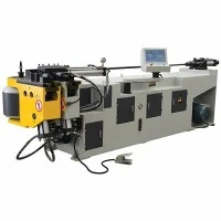



Electric Tube Bender For Thin-Wall Tubes
Electric Tube Bender for Thin-Wall Tubes | Technical Product Specification
The [Model Series Name] Industrial Electric Tube Bender is engineered for high-precision, deformation-free cold bending of thin-wall metal tubes. Utilizing fully digital, closed-loop multi-axis servo control, the architecture addresses the primary failure modes of thin-wall tube processing: radial flattening, outer-radius thinning, inner-radius wrinkling, and structural collapse.
Constructed on a heavy-gauge, stress-relieved structural steel bed, the machine integrates real-time spring-back compensation algorithms. It is built for manufacturing environments in automotive, aerospace, and high-end fluid systems that demand strict geometric repeatability in stainless steel, aluminum, and high-strength alloy tubing.
Technical Specifications
|
Technical Parameter |
Standard Specification Range |
|
Max. Tube Outer Diameter (OD) |
16 mm – 89 mm (Custom capacities up to 120 mm available) |
|
Wall Thickness Capacity |
0.5 mm – 2.0 mm (Material tensile-strength dependent) |
|
Minimum Centerline Radius (CLR) |
1.0D – 1.5D (Tooling and wall thickness dependent) |
|
Max. Bending Angle |
180° + Programmable over-bend for spring-back compensation |
|
Bending Axis Accuracy (Y-Axis) |
+/-0.05° (Direct-drive servo precision) |
|
Feeding Axis Accuracy (X-Axis) |
+/-0.05 mm |
|
Rotation Axis Accuracy (C-Axis) |
+/-0.05° |
|
Drive Architecture |
Absolute multi-axis AC brushless servo motors |
|
Control Interface |
Industrial CNC with 15-inch multi-touch industrial HMI |
|
Power Supply Requirements |
12 kW – 24 kW (3-phase, 380V/480V, 50/60Hz) |
Key Features
Stress-Relieved Monoblock Bed: The machine frame is laser-cut from heavy plate steel, subjected to thermal stress-relief annealing, and finish-machined on a 5-axis gantry milling center to ensure permanent mechanical alignment under peak loads.
Backlash-Free Direct Servo Head: Eliminates mechanical play associated with traditional hydraulic or planetary gearboxes, securing consistent angular accuracy across multi-thousand-piece production runs.
Programmable Mandrel Extraction: Features an early-extraction pneumatic/hydraulic booster system that retracts the mandrel prior to bend completion, eliminating inner-wall tearing on thin-gauge materials.
Synchronized Pressure Die Boost: Delivers real-time auxiliary push-force during the bend cycle, neutralizing material elongation on the outer radius and keeping wall-thinning below 10%.
Intelligent CAD/CAM Integration: Direct import of STEP/IGES tubing files, automated collision detection, and dynamic spring-back database correction directly from the HMI.
Working Process
Material Loading & Clamping: The thin-wall tube is fed onto the mandrel extension. The hydraulic clamp die engages the outer diameter across a 180° arc to distribute clamping forces without radial indentation.
Mandrel Positioning: The internal plug or multi-ball mandrel advances precisely to the tangent point to provide structural internal resistance against ovality and collapse.
Servo Bending & Dynamic Boost: The bending arm rotates via the primary servo motor while the pressure die and booster cylinder feed material synchronously into the forming zone.
Mandrel Pre-Retraction: The mandrel retracts fractionally before the clamp and pressure dies release, preventing surface dragging or tube binding.
Component Ejection: The finished part indexes clear of the tooling zone for downstream inspection or welding preparation.
Applications
Automotive Exhaust & Fluid Delivery: Stainless steel and titanium exhaust headers, turbocharger lines, and fluid conduits requiring smooth interior boundary layers.
Aerospace Structural Components: Lightweight aluminum alloy framing, environmental control ducting, and hydraulic lines meeting strict weight-to-strength ratios.
HVAC & Refrigeration Loops: Copper and aluminum return bends and evaporator coils engineered for leak-free, zero-wrinkle performance.
Medical Equipment Infrastructure: Surgical support frames, imaging device tubing, and diagnostic cart structures requiring clean aesthetics and tight dimensional control.
Tooling & Configuration
Thin-wall tube integrity depends heavily on matching tooling geometry to the specific material elongation properties:
Mandrel Assemblies: Single-ball, multi-ball (articulated), and form-matched plug mandrels machined from Ampco-18 aluminum bronze or hardened tool steel to reduce sliding friction.
Wiper Dies: Carbide-tipped or aluminum-bronze wiper dies positioned tightly against the tangent point to suppress inner-radius crowding and wrinkling.
Forming Dies: Matched-radius clamp and pressure dies CNC-machined to exact tube OD tolerances.
Customization
Factory integration often requires tailored mechanical configurations. Available engineering modifications include:
Extended Bed Lengths: Supporting raw stock up to 6,000 mm for long architectural or structural members.
Multi-Stack Tooling: Compound bending heads supporting dual-radius or multi-stack configurations in a single part cycle.
Automation Cells: Integration with industrial robotic loading/unloading gantries and inline optical measurement stations.
MES Connectivity: Protocol integration via OPC-UA for factory-floor data tracking and remote diagnostics.
Quality & Manufacturing Verification
Manufacturing workflows incorporate rigorous shop-floor metrology and testing protocols prior to factory release:
Structural Machining Validation: Laser interferometry alignment verification on all linear guideways, ball screws, and servo mounting planes.
Metrology & Sample Testing: Each machine undergoes a 72-hour continuous dry-run followed by live metal sample bending. Output parts are inspected using 3D optical scanning arms to verify angular recovery and wall-thinning ratios against CAD models.
Electrical & Safety Compliance: Control panels are built to NFPA 79 and CE standards, integrating industrial-grade switchgear (Siemens, Schneider) with full schematic documentation.
FAQ
Q: How does the machine prevent thin-wall tube flattening and wrinkling during tight-radius bends?
A: Prevention relies on a coordinated three-point tooling system: an articulated internal mandrel supports the inner wall against radial collapse; a closely fitted wiper die prevents material lifting at the tangent point; and a programmable pressure die booster supplies synchronized axial push-force to control outer-wall thinning.
Q: What is the maximum allowable wall-thinning percentage on 1.0 mm wall stainless steel?
A: When utilizing matched tooling configurations (such as an articulated mandrel and wiper die) alongside the programmable pressure boost, wall-thinning on a 1.5D centerline radius is typically maintained below 10%, meeting standard aerospace and automotive requirements.
Q: Does the CNC control system calculate spring-back automatically for different alloys?
A: Yes. The HMI includes an editable material elasticity database containing historical recovery metrics for standard grades of stainless steel, aluminum, and carbon steel. The software applies pre-programmed compensation angles during code generation, supported by live test-bend calibration tools.
Q: What utility infrastructure is required on the shop floor for installation?
A: The machine requires a standard 3-phase industrial power supply (380V/480V based on regional specification) and a clean, dry compressed air supply delivering a minimum of 6 bar (0.6 MPa) for pneumatic clamping and lubrication circuits. No specialized hydraulic foundation pits are required.
Q: What is the standard lead time for replacement tooling and wear parts?
A: Standard radius mandrels and wiper dies for common outer diameters (25 mm to 50 mm) are maintained in inventory for dispatch within 5 to 7 business days. Custom radius tooling requires 15 to 20 business days following engineering drawing approval.
Q: What technical documentation and post-purchase support are included?
A: Each delivery includes complete electrical schematics, pneumatic/hydraulic circuit diagrams, PLC backup data, an English operation and maintenance manual, and an industrial Ethernet port for remote diagnostic assistance. On-site commissioning and operator training are available upon contract agreement.
Hot Tags: electric tube bender for thin-wall tubes, China electric tube bender for thin-wall tubes manufacturers, suppliers, factory, CNC Pipe Bending Machine, Copper Pipe Bending Machine, Furniture Pipe Bending Machine, Rotary Draw Metal Tube Bending Machine, Square Tube Sawing Machine, Thick Wall Tube Circular Saw Machine
You Might Also Like


Send Inquiry